
Doppler
correction using segmented
Germanium
detector
G.Turk1, A.J.Boston1, J.R.Cresswell1, S.Gros1, A.R.Mather1,
B. McGuirk1, P.J.Nolan1, J.Norman1, J. Sampson1, J.Thornhill1, C.Santos2,
J.Simpson2, I. Lazarus2, C.J.Hall2, W.I. Helsby3, R.A. Lewis4
1Department of Physics, University of
Liverpool, Liverpool, UK.
2CCLRC Daresburg Laboratory, Warrington,
Cheshire, UK.
3IReS Strasbourg, Strasbourg, France.
4School of Physics and Material
Engineering, Monash University, Melbourne, Australia.


129 mm
43 mm


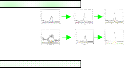
Doppler correction
The
Doppler effect is described by the following formula:
E = E0(1+v/c cos(q))
where
v/c is
5.6 % and q
is the angle between the beam and the correcting element
of the detector. For the incorrected data, the angle is 90 degrees.
The
correction is done for different parts of the detector. Showed is first the initial
spectrum. This is taken from the raw data. The two other spectra show an improvement
in energy resolution if a correction by sector and segment are performed.
The resolutions of the peak are shown with the figure.
The
129 mm distance cannot be corrected as well as the closer distance. After the
sector correction it is not improving. The smaller distance however can be improved
with the segment correction. Hence the correction within a segment, using
pulse shape analysis, can only be beneficial here.

31.0 keV
19.6 keV
19.6 keV
66.8 keV
26.5 keV
23.5 keV
Doppler correction
Pulse shape analysis

The
next step in improving the resolution is utilizing the pulse shape analysis.
It involves looking at the shape of each pulse.
A
scan across the front face of the detector has been performed, resulting
in a good characterization of the detector. An intensity plot can be
made and show the non-coaxial electric field at the front of the detector
very well.
The risetime response for different
parts of the detector are indentified. T30,
T60 and T90 risetimes are calculated on an event by event basis. The
risetime distributions as a function of radius are shown. A linear fit has
been performed on the distribution for all the segments. For a given risetime
the corresponding radius can be calculated.
Further
work is required to Doppler correct the data with the pulse shape analysis.

T90
T30

High
Purity Germanium detector have been used in gamma ray spectroscopy for years. The
key aspect that makes them particular suitable is the excellent energy
resolution. The last 5 years the development of the
Ge-detectors moved on towards segmented germanium
detector. These kind of detectors have the Germanium crystal electricly segmented
into several individual parts. The segmentation improves the position resolution
and makes them suitable for pulse shape analysis. By digitisation of the pulse
shape a more precise interaction position can be achieved.
Using this technique a better Doppler correction can be
performed.
An
experiment has been done at the university of Cologne using the tandem
accelarator. A 70 MeV 37Cl
beam incidents on a deuterated Ti-foil target of 500 mg/cm2 thickness with Cu
backing of 200 mg/cm2. This induces the reactions:
D(37Cl,
p)38Cl
D(37Cl,
p)38Ar
The
main interest goes out to the 2+ to 0+ which
produces a 2167 keV gamma ray. The v/c of the recoils is
5.6% which should be sufficient for the Doppler correction.
Equipment and setup
Electric field lines
Holes
Electrons
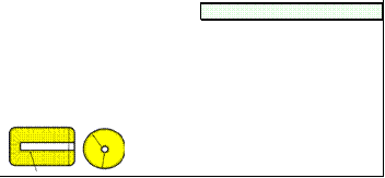
A
24-fold segmented segmented detector is used
in the experiment. The detector has a 80
mm long high purity n-type crystal with a diameter
of 65 mm. The detector is electrically segmented into 4 rings
and 6 sectors. Each segment has an
individual outer contact and a common center
contact.
The
detector was placed at two different distances from the target, i.e. 43
mm and 129 mm. There is a large difference
in energy resolution of the 2167 keV
peak for the 2 distances. The difference in
energy resolution is a result from this.

129 mm
43 mm
Eu 152 source
The
data for the detector was digitized by a specially
designed data-aquisition system. It consists out of 7 GRT4 VME modules.
Each module has 4 input channels each
consisting out of an amplifier and 14 bit 80
Mhz flash ADC.


Introduction


Intensity
plots of the two rings of the detector
Risetime
distribution
Email: gt@ns.ph.liv.ac.uk
